TAMC532

32 x 12/14 Bit 50/75 Msps ADC for MTCA.4 Rear-I/O

  • usable in AMC and MTCA.4 environment
  • 32 analog input channels
  • 75 Msps at 12 bit resolution (optional 50 Msps at 14 bit resolution)
  • very powerful on-board clocking structure
  • 8 channel trigger I/O to synchronize multiple TAMC532
  • flexible interfacing without changing the AMC
  • rear I/O via zone 3
  • powerful Kintex-7 FPGA allows adaptations to custom requirements


Product status: Active

Operating Temperature Range 0 °C to +70 °C RoHS compliant

The TAMC532 is an Advanced Mezzanine Card (AMC) according to MTCA.4 (MicroTCA Enhancements for Rear I/O and Precision Timing). 32 analog input channels allow sampling of analog signals with 75 Msps at 12 Bit resolution (optional 50 Msps at 14 Bit).

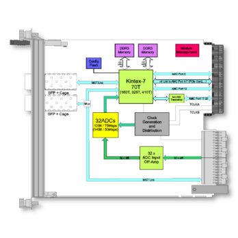
The TAMC532 utilizes Back-IO via Zone 3 to interface the ADCs with the signal conditioning located on the µRTM. This modular concept allows adapting the TAMC532 to nearly any analog input requirement without changing the AMC itself.

A very powerful on-board clocking structure enables using the TAMC532 in nearly all kind of clocking scenarios. A self-clocked application as well as synchronizing multiple TAMC532 is possible, allowing applications with up to several hundred simultaneous sampled channels.

Data readout can be done via several interfaces like e.g. PCI-Express or two SFP-cages in the front panel.

The on-board DRR3 memory can be used for data buffering in triggered applications that require subsequent readout. Assuming sufficient data fabric bandwidth, the DDR3 memory can also be used as double buffer, allowing infinite data acquisition.

Up to eight backplane triggers are available, each configurable as input or output.

The TAMC532 is equipped with a powerful Kintex-7 FPGA for data preprocessing and transfer. By default, the Kintex7 FPGA is configured with a firmware that provides a very functional readout system and full control over the numerous clocking and trigger options. It can also be adapted to customer needs if necessary.

In-circuit programming and debugging of the FPGA design (e.g. using Xilinx ChipScope) is supported. The Program and Debug Box TA900 or the standard Xilinx JTAG header allows access to the module while it is inserted in a system. In addition to the module's JTAG Chain, the TA900 allows access to the UART of the on-board Module Management Controller (MMC) and to two user pins of the FPGA. If a UART core is implemented in the FPGA, serial communication via the TA900 is possible.

The TA900 can be accessed by USB 2.0 and by a 14-pin JTAG Header (e.g. for connecting a Xilinx Platform Cable).
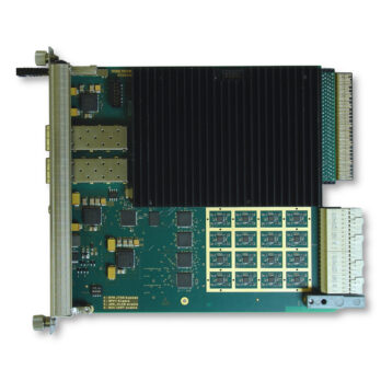
Mechanical Interface Advanced Mezzanine Card (AMC) Interface conforming to PICMG® AMC.0 R2.0 (Advanced Mezzanine Card Base Specification)
Module Type: Double Mid-size Module
Electrical Interface AMC Port 0; AMC Port 4-7, AMC Port 12; AMC Port 17-20 via M-LVDS Transceivers, TCLKA + B (Protocol support and port usage depends on FPGA programming)
IPMI Version 1.5
Front Panel LEDs Blue Hot-Swap LED
Red Failure Indication LED (LED1)
Green Board OK / User LED (LED2)
FPGA XC7K70T-1FBG676C or compatible
DDR3 Memory MT41J64M16LA or compatible
Flash N25Q256 or compatible
ADC TAMC532-10R : AD9637 (12 Bit resolution)
TAMC532-11R : AD9257 (14 Bit resolution)
SFP+ 2 x SFP+ Cage
Analog Input Voltage 0V ±1V (differential)
Number of Channels 32
I/O Connector 2 x 30 pair ADF Connector according to MTCA.4
Power Requirements Management Power: 70mA typical @ +3.3V DC
Payload Power: 2A typical @ +12V DC
max. Current Draw as per Module Current Requirements Record: 5A
Temperature Range Operating: 0°C to +70°C
Storage: 0°C to +70°C
MTBF 272000 h
Humidity 5 – 95% non-condensing
Weight 385 g

PRODUCT VARIATIONS

TAMC532-10R

32 Analog Inputs (12 Bit, 75 Msps) for MTCA.4 Rear-I/O

Kintex-7 (XC7K70T), 2x 256 MByte DDR3; 32 Analog Inputs (12 bit); 75 Msps

TAMC532-11R

32 Analog Inputs (14 Bit, 50 Msps) for MTCA.4 Rear-I/O

Kintex-7 (XC7K70T), 2x 256 MByte DDR3; 32 Analog Inputs (14 bit); 50 Msps

ACCESSORIES

32 x Analog-In MTCA.4 µRTM for Class A2.1 for TAMC532

Program and Debug Box

SOFTWARE

Device Driver for Multichannel ADC Boards

Data Sheet

Data Sheet

Data Sheet - Issue 1.1.0

User Manual

User Manual - Issue 1.1.0